Exhaust Liner System
Gas Turbine Exhaust System Liner

Gas Turbine Exhaust Liner
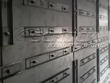
At the heart of our system is our proprietary liner system. The system starts with large diameter stainless steel liner studs, hand welded to the casing plate at a close pin spacing pattern. Followed by liner support hardware, and 11 gauge 409 SS liner laser cut to perfection. We secure in place with complete clamping channel coverage at all stud locations and complete with our nut torquing procedure to ensure no voids in liner laps but allows for thermal movement. Our "cold" liner system is also applied at all field joints, to ensure consistent casing temperatures.
Your liner system is not a "one size fits all". We custom design each system and decide using CFD modeling and Combustion Turbine data to determine which liner system to apply throughout the system.
LINER SYSTEM VARIATION
- Schock Turbulent Liner : Turbulent liner is applied in the most harsh conditions
- Schock Intermediate Liner : Intermediate liner is typically utilized once the flow becomes laminar
- Schock Stack Liner : Stack liner is applied in areas where flow is uniform
EXHAUST LINER COMPONENTS
-
Liner Sheets
We select the liner thickness and material type based on the Gas Turbine operating conditions. Our liner sheets are laser cut for accuracy and consistency.
-
Liner Pins
We also select the liner pin diameter, length, material type, and spacing based on the operating conditions. Our pins are custom fabricated to spec., and individually welded without any automated processes. This is to ensure the proper penetration without fail to the casing plate.
-
Liner support
Our Exhaust Liner is supported in the insulation cavity as required to ensure no liner gaps, consistent torquing of the hardware, and maintain a constant insulation cavity thickness.
-
Liner Clamping
Another important liner component, is the clamping method used on top of the liner sheets. We use variations of flat bar (round stacks), formed channels, formed angles, and custom made liner washers. All of which ensure the liner system can "float" or grow without subjecting the insulation cavity to harsh Exhaust System Flow.
-
Hardware
We use custom cut washers based on application. They are typically either round or rectangular and laser cut to perfection. They are applied in conjunction with Stainless Steel Nuts.
-
Torquing
The proper torquing techniques is critical for the liner system to work properly. Over many years, Schock has developed a systematic approach to install, and torque.
-
High Temperature Insulation
Our core insulation system in completely inorganic and exhibits no smoke generation or outgassing in service. It has low thermal conductivity and excellent resistance to thermal shock.
-
Insulation Protection
We use a variety of methods to further protect our insulation cavities when they are potentially subject to flow. These range from ceramic, Stainless Steel, and other types of cloth or mat.
-
Shipping Protection
Lastly, and important component for our liner system, is protection during shipment or storage. We use a reinforced sheet that fully encapsulates our insulation system where exposed for field splicing.
